Case study: a small custom hardware / software project
If you have never considered letting someone design a new electrical circuit to solve a real‑life problem, this article is for you.
One day a friend came to me with a problem: he needed a safety system in his mother’s kitchen to ensure she didn’t leave the stove running. He got the idea from a well‑known system called a dead man’s switch or driver vigilance device, commonly used on trains to prevent accidents if the driver falls asleep — a creative way to look after elderly people.
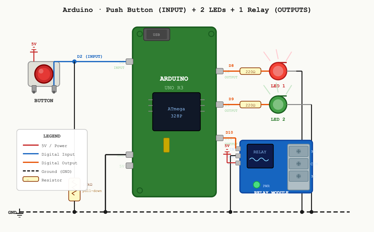
He was already a DIY person, so his first idea was to connect a bunch of relays (electromechanical switches) together. That was how digital computers were built in the 1940s — it requires lots of parts, wiring, relays, and maintenance. Totally doable, but not the smartest approach today. Next idea was to buy an Arduino (a common prototyping platform for hobbyists) and write some software.
Getting closer — turning a hardware problem into a software problem (switching devices on and off based on well defined logic) is how 99% of modern electronic devices work. Pick any device around you (washing machine, intercom, car): real‑world components (water valves, microphones/speakers, fuel injectors) are controlled by software running on a small computer called a microcontroller. The secret sauce is software. It’s practical and cheap: no rewiring when requirements change, just upload new firmware.
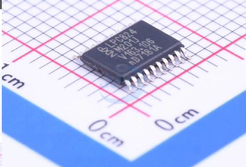
For the record, this is what a microcontroller looks like. It’s an integrated silicon chip with a processor, RAM, flash storage, and peripherals (timers, GPIO, UART, and many others) all in one package. This one has 8 kB of RAM and 32 kB of flash — kilobytes, not megabytes or gigabytes — a very different world from your desktop computer, but you’d be surprised how much functionality fits in. This is a medium‑sized device; smaller variants exist.
When my friend asked me to write the firmware, he added a few requests. Besides the main push button, which must be pressed frequently to prevent the stove shutting off, he wanted the kitchen door involved: if his mother left the kitchen with the stove on, the device should shut the stove off immediately and start a timer that blocks switching it on for a while. He also wanted LEDs to display system status and the ability to adjust timing parameters after release based on real testing with his mother. All feature requests were accepted — developing them was only a few hours of work (and AI could generate the code even faster now).
At that point we could have finished the project using off‑the‑shelf parts and firmware. For a paying customer it would be a cheap project (a few hundred EUR): use Arduino hardware and simple electronic parts. But then we agreed to add more inputs, a second relay output, and one important thing: optical isolation to protect the end user — his mother.
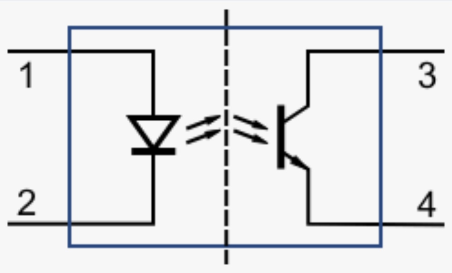
When controlling mains voltage (230 V) in a device that users touch (the push button), it’s important to do things correctly. If a relay fails while the user is touching the button, dangerous voltage could travel through wires, components, and the button and injure the user. Optical isolation solves this by dividing the electronics into two zones with no direct electrical connection. The two zones communicate via an optocoupler, which transmits the signal as light instead of electrical current. In the image, the left side drives the relay input (light or no light inside the chip). The right side is a phototransistor that conducts or not depending on the light.
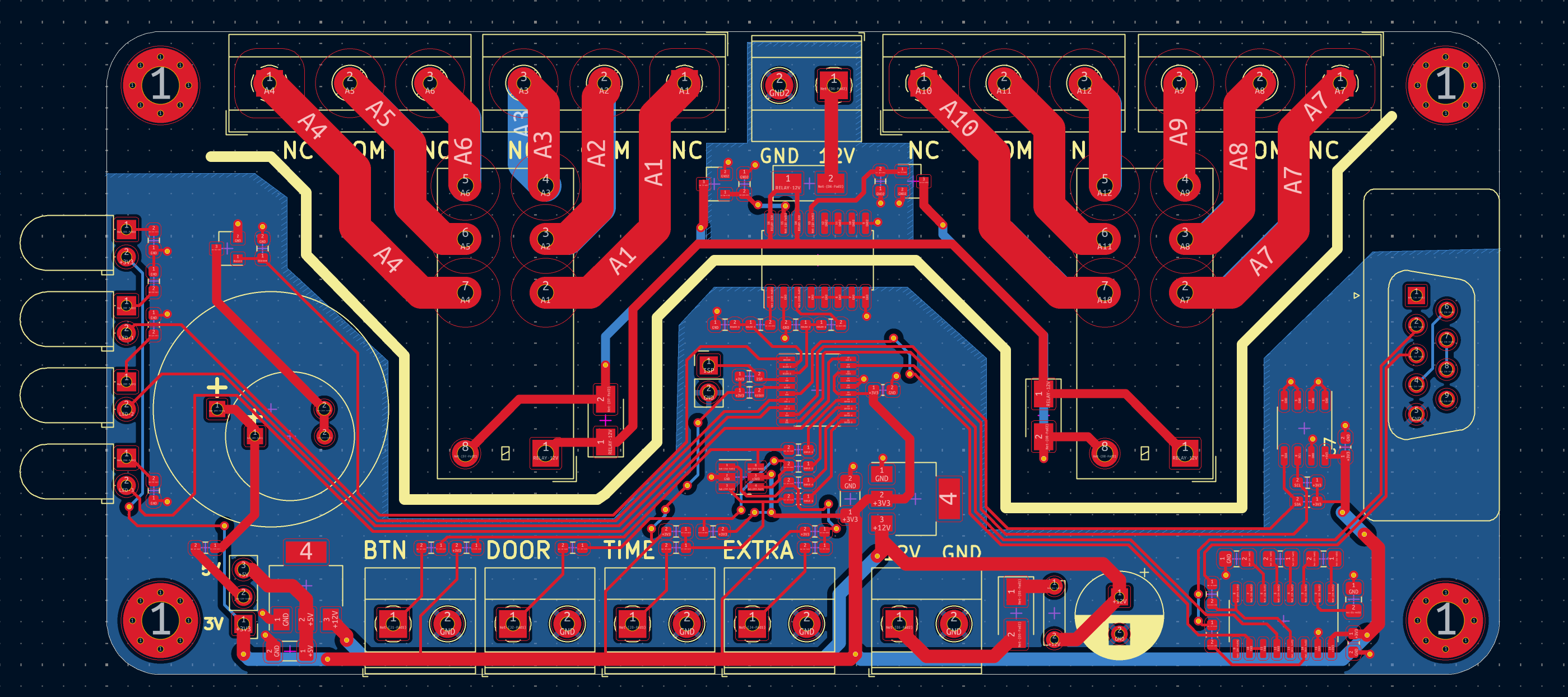
Given the added complexity, I decided to design a custom printed circuit board (PCB). The estimate was 1–2 workdays, not more than assembling off‑the‑shelf components. A custom PCB was the right choice: it looks better, is more reliable, reduces maintenance from loose wires, and scales to production. To design the PCB we first draw the logical connections — the schematic, shown below.
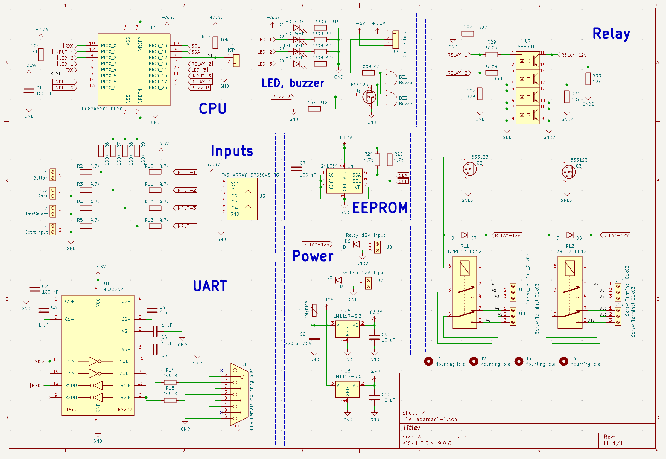
Then we convert the schematic into the physical board, routing every trace. We use narrow traces for digital signals and wider traces for power or relay currents (which must handle a few amps). Red is the top copper layer, blue the bottom. The white line marks the two optically isolated areas. This is a simple two‑layer PCB, though multi‑layer boards are common; modern cell phones often have eight or more layers. Schematic work is engineering; board layout involves art. Two boards can have identical functionality, but only one might make clients say “wow, what a beauty,” even if they’ve never seen a PCB before.
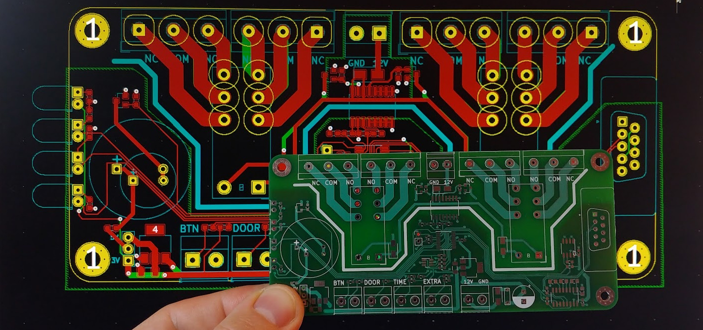
Back then I sent the design files to a local PCB manufacturer and bought components from two different stores. Nowadays we usually order the assembled boards from China. After soldering the components, I spent a day developing and testing the firmware. Today it would be mostly AI: a few minutes to prompt, some waiting, and a couple of hours of testing. Look how good the PCB turned out!
If the client had not been my friend, I would have charged around 1,000 EUR (I accepted services instead). You might say 1,000 EUR is a lot for a simple device — and our Chinese friends might produce it for €8.50. If you can buy a product that fits your needs, go ahead. Custom hardware is justified when you cannot buy exactly what you need. Large factories aim for millions of units, so their per‑unit development cost is much lower than 1,000 EUR.
To close the story: here’s the sad part. Around 20% of IT projects are delivered but never used, and this was one of them. Six months after delivery my friend told me he still hadn’t installed it. You might blame clients who don’t know what they need, but even experienced IT people can make this mistake. I’ve been there too — but that’s another story.