Frequently Asked Questions
Everything you might want to know about hardware, software, and working together.
A PCB is a Printed Circuit Board. Very short definition: it’s the flat board (usually green) that holds and connects electronic components in almost every device. Copper traces on the board replace loose wires, forming all the electrical connections. Components (chips, resistors, connectors, etc.) are soldered onto the PCB. Without a PCB, you’d have a mess of individual wires; with a PCB, the circuit is compact, reliable, and manufacturable.
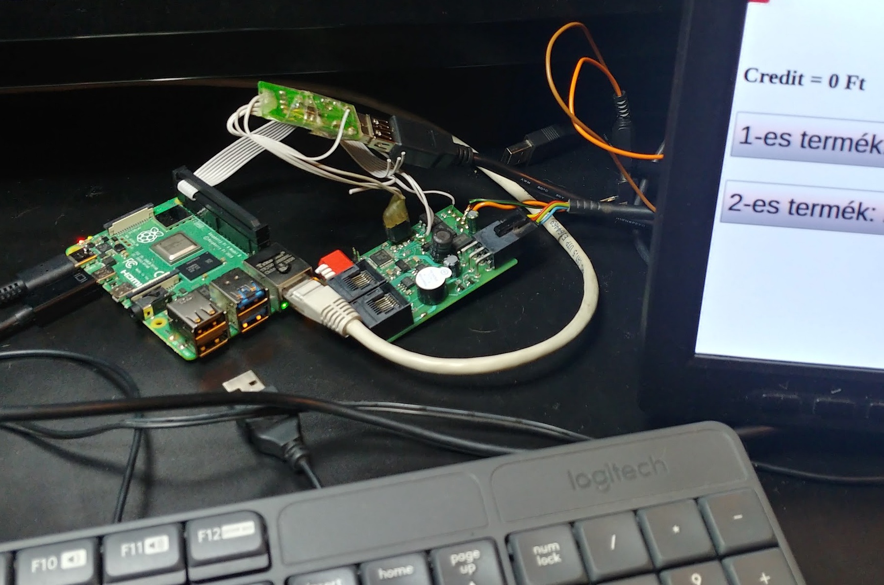
Depends on what stage are you at your project. At the beginning, with fresh ideas to validate, you definitely should start with an existing product like Arduino or Raspberry Pi. You can save money and time by focusing on the MVP software. This is the best way to be able to do an early presentation and get funded. On the other hand, your product would look like this one below, with Raspberry Pi and two other PCBs, a touch screen and a keyboard, mess of wires, quite a chaos:
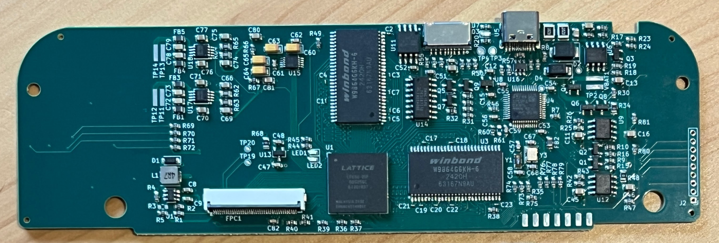
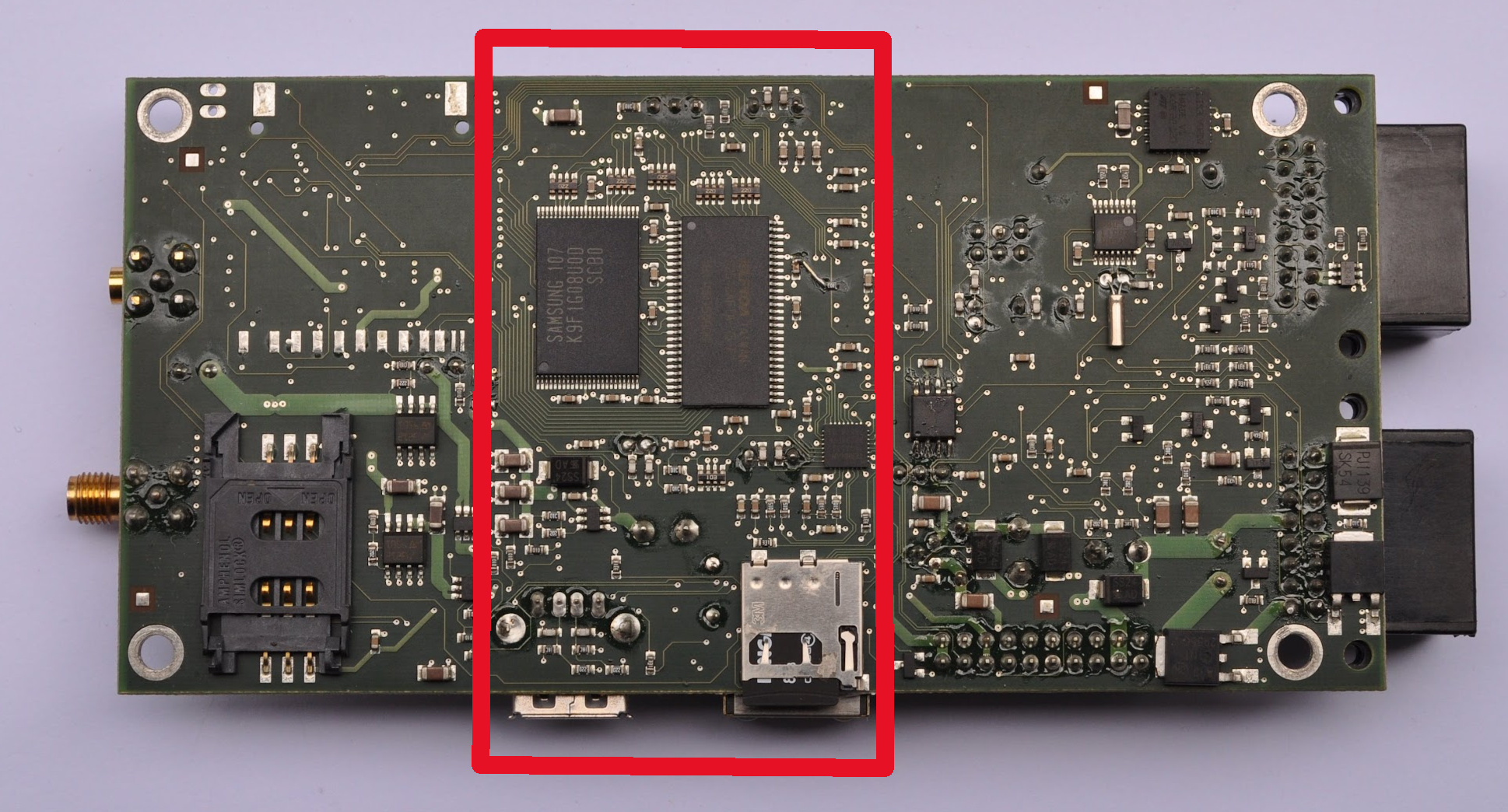
Down the road, when you are really confident about your idea, have more money to continue, you should have a custom PCB which includes all your components. There are many reasons to do that. Your product does not only look more professional and sellable in a form of a single PCB solution, but also scalable to production, smaller, more reliable, could consume less energy. On the image below, you can see a production ready custom PCB which implements four other PCBs all in one, with the red marker on the area of a Linux embedded computer (similar to Raspberry Pi, but less powerful, cheaper, and consumes less power, tailored to the specific project).
An embedded engineer builds the electronics and low‑level software that live inside devices (phones, cars, appliances, machines, etc.). In practice, they:
Design and program small computers (microcontrollers)
Choose chips (e.g., ARM, ESP32, PIC) and key components. Write firmware in C/C++ (sometimes Rust/Assembly). Implement state machines, control loops, and device logic
Connect hardware and software
Configure GPIO, ADCs, timers, PWM, interrupts. Implement communication protocols: UART, I²C, SPI, CAN, USB, etc. Write simple drivers for sensors, displays, motors, relays, radios.
Work with electronics / PCB design
Create schematics and PCB layouts. Understand power, grounding, signal integrity, protection circuits.
Debug and optimize on real hardware
Use oscilloscopes, logic analyzers, JTAG/SWD debuggers. Track down timing bugs, noise issues, crashes, and lockups. Optimize for memory, speed, and power consumption.
Integrate into products
Make the firmware robust for production and field use. Support manufacturing tests, firmware updates, and diagnostics. Document behavior and interfaces for other teams.